Using the Motor Controller
Table of Contents
The Raspberry Pi has only a single PWM output. The Dagu Rover 5 chassis has 4 motors and 4 optical encoders that need reading as well. So my approach was to get a PWM servo/logic controller that could control the Dagu Motor Controller and additionally some servos for the camera pan/tilt.
Motor Control #
The Dagu Motor Controller has two distinct functionalities.
- Controlling the motor outputs based on a PWM input and direction input
- Multiplex the signals from the encoders on the motors to provide signals when the wheels rotate, and how fast.
For the PWM control I’m using an Adafruit 16 channel PWM Servo and LED controller. It has 12 bit resolution and allows 4096 steps for the PWM control. It also allows constant on or off signals for a specific output.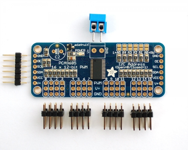
Each of the outputs consists of the following signals:
- PWM output, programmable
- V+, the “power” voltage. This is useful for driving servos and not used for the Dagu motor controller
- GND, the ground.
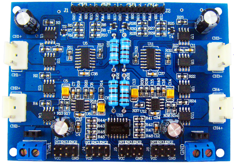
The Dagu Motor Controller provides the following pins per channel:
- GND, the ground
- PWM, for controlling the voltage applied to the specific motor channel
- DIR, the direction in which the motor should rotate. High is forward, Low is backward.
- CUR. This is an output port, which indicates the current going throught that channel as an analog voltage. The scale is ca 1V on the pin per 1A of current going through the motor. Voltages are much easier to measure than currents, so this signal will be interesting.
I want to control the direction and speed of each motor directly. Based on the signals that I can get out of the PWM controller, I need two channels per Dagu motor channel to control PWM and the direction (High or Low).
I have now per channel the following connections (Dagu controller -> PWM):
- GND -> GND (channel 0)
- PWM -> PWM (channel 0)
- DIR -> PWM (channel 1)
- CUR -> not connected yet. This will go to an ADC.
Python code for this with more explanation coming soon.
Rotary Encoder #
The second functional element of the Dagu controller is the multiplexer for the two-sensor rotary encoder. Combining the interrupt output of this encoder with a GPIO port on the Raspberry Pi makes processing of these signals possible.
The GPIO library for Raspberry Pi also supports asynchronous callbacks when an event happened on a specific GPIO port.
I’m using this to count the interrupts / steps in the background. Later I want to extend this to add event triggers when a specific threshold or delta of steps is reached.
For now I’m using these counts to output some information on the console while the motors are running back and forth at different speeds using the PWM signals.
Abbreviations:
- PWM: Pulse Width Modulation. A signal is repeated at frequency (e.g. 60Hz). During each cycle, the signal can be switched on and off. Depending on the element receiving this signal it’s either used to reduce the current, movement period, or for servos define a specific position (angle).
- ADC: Analog Digital Converter: A circuit that can provide discrete digital values for an analog voltage. Recording sound is done like that, or measuring voltages.
- GPIO: General Purpose Input Output. Programmable input and output pins that can be controlled via software.